Wicking Rate Apparatus
Design Brief & Constraints
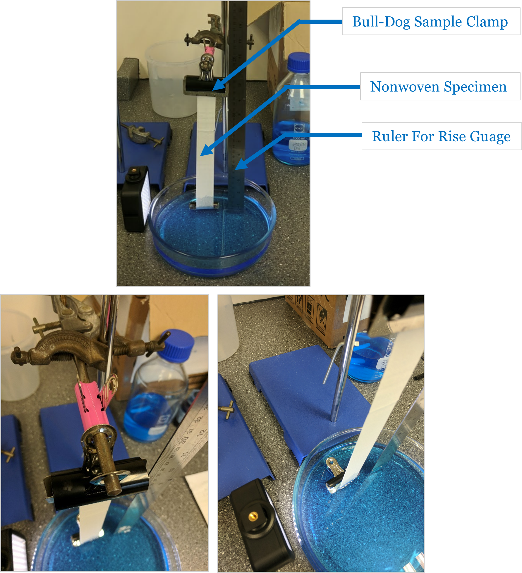
Previous wicking rate measurement set-up
The above image details the previous set-up used to test the wicking rate of fabric specimens. Nonwoven & textile samples are comprised of porous channels that act as capillaries, utilising the surface tension of the liquid to drive flow through their structures. This is property, known as wicking, is an important parameter contributing to the liquid handling capability of the textile. A standard test can be carried out to quantify this property by measuring the height of liquid rise as a function of time through the fabric,
The previous test configuration was compromised by many shortcomings, including:
User variance in both set-up and measurements
Difficult test set-up
Unprofessional presentation
The objective of the project is to design a standardised testing rig allowing for consistent test set-up to ensure repeatable testing of nonwoven textiles. This led to the following design constraints:
Designed in accordance with standard test method NWSP 010.1.R0 (20) – Part (c) the liquid wicking rate (capillarity).
The apparatus must be simple and consistent in its set up
Comprised of 3D printed parts and standardised components were necessary.
Corrosion Resistant
Cater for various specimen lengths
Design Concept
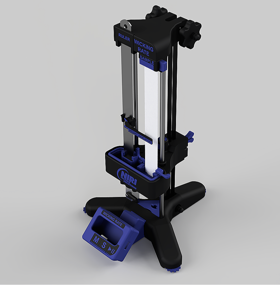
Wicking Apparatus: Isometric
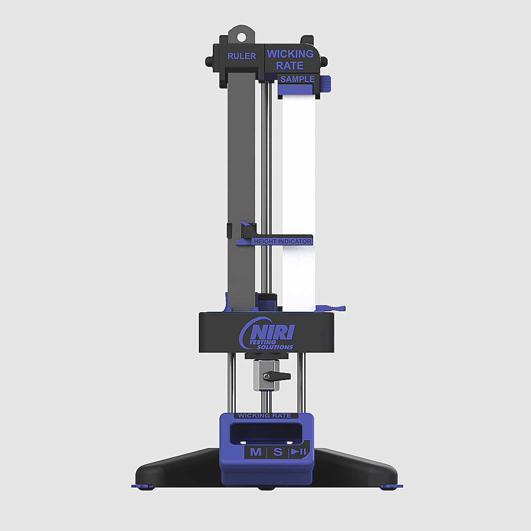
Wicking Apparatus: Front facing elevation
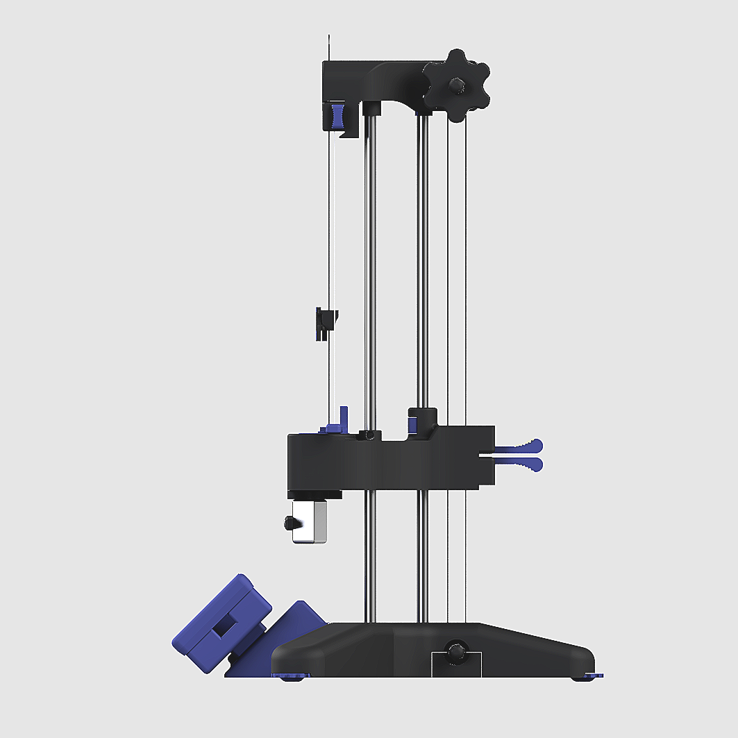
Wicking Apparatus: Side facing elevation
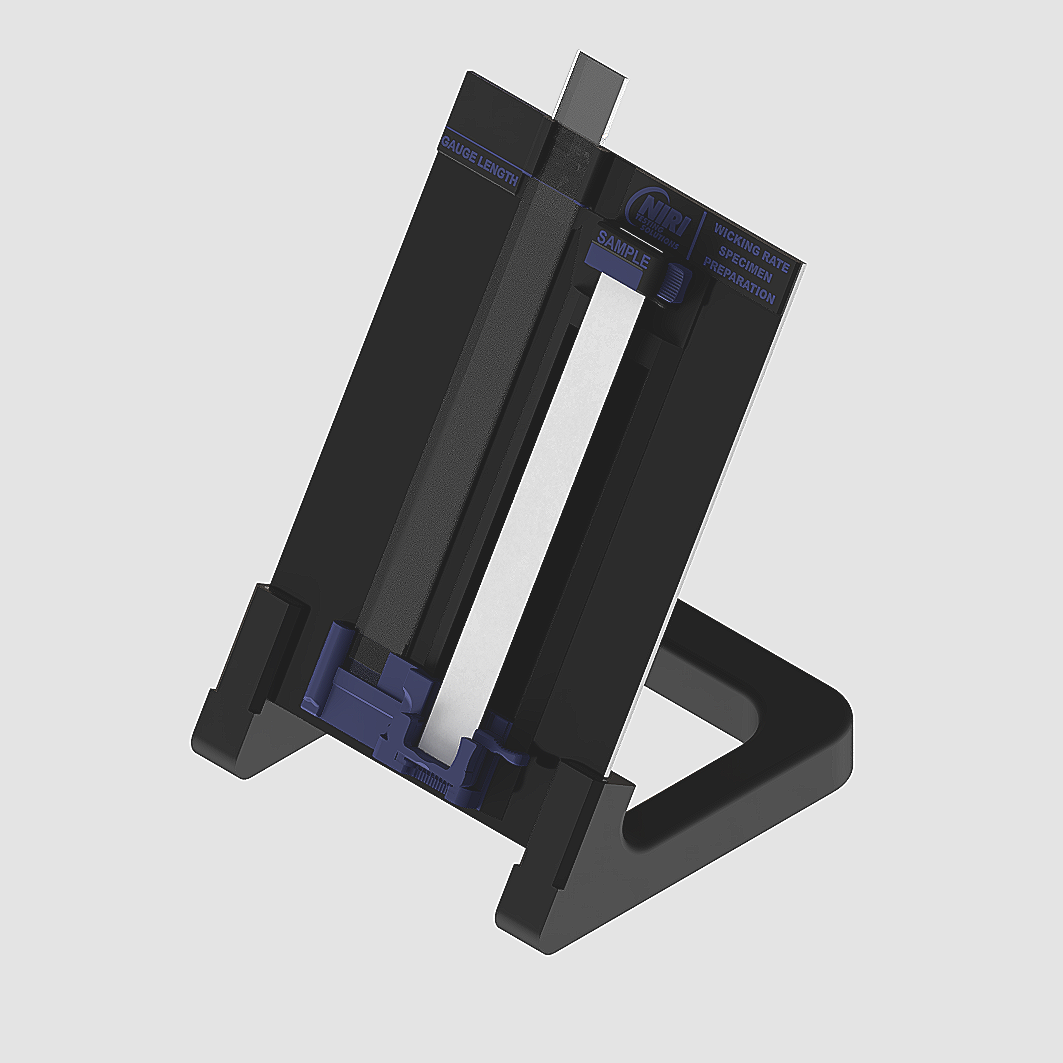
Specimen preparation widget
The concept focuses on providing the operator with a simple-to-use testing apparatus that conforms to NWSP 010.1.R0 (20) – Part (c). The apparatus centres on a repeatable operator experience that removes the awkwardness of testing fabric capillarity. Key features include:
Specimen preparation widget
Height-adjustable water trough with
Removable magnetic trough insert for ease of cleaning
Magnetic sample clamps
Magnetic height indicating slider
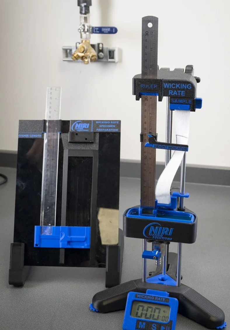
Built-in timer
Concept Features: In-Depth
Specimen Preparation Widget
The specimen preparation widget allows the operator to set the movable trough height. The operator mounts the specimen within the widget, adjusts the positioning until the specimen is taught and reads off the value from the transparent ruler against the marker, which corresponds to the gauge length of the magnetic clamping system on the wicking apparatus—making the apparatus capable of handling various specimen sizes, for the operator’s convenience.
Height-Adjustable Trough
Once the operator has determined the suitable trough height for the specimen, they can manually adjust the water trough height for testing until the ruler aligns with the marker at that value. This will ensure there is sufficient tension on the specimen for testing. The trough is connected to a pulley with two knobs at the top of the wicking apparatus that can be adjusted. Turning the knobs will smoothly translate the trough along the stainless steel rods via the three embedded linear bearings. Once at the desired height, the position can be locked.
Removable Magnetic Trough
Once the operator has tested the samples, the trough can be drained via a ball valve. A magnetically integrated trough insert that creates a seal with the height-adjustable trough body can then be removed and wiped clean.
Magnetic Sample Clamps
Neodymium magnetic clamps are designed to position both the top and bottom of the specimen, allowing the operator to easily and repeatably mount the specimen to the wicking apparatus.
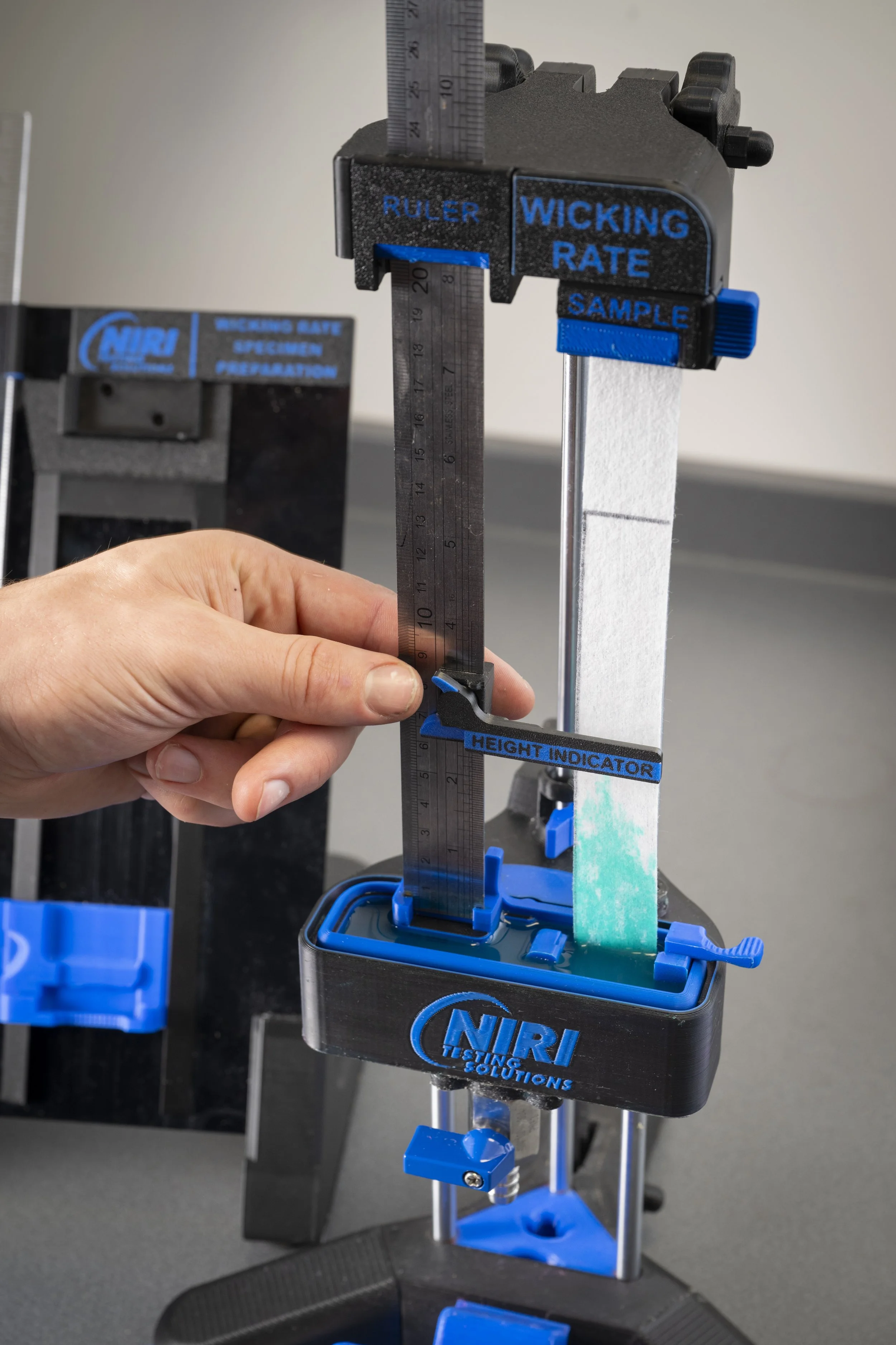
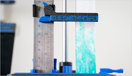
Magnetic Height Indicator
During the test, the operator must take readings of the height to which the liquid has risen through the sample, after specific time intervals. The operator moves the magnetic indicator, which slides over the stainless steel rule, so that it is aligned with the height of the liquid, and then reads off the value at the specified time stamp.
Finished Prototype