Filament Wrap Creel
Design Brief & Constraints
Man-made fibres tend not to get too much thought outside of those within the textile, nonwoven and composites industry. Synthetic fibres are significant to the plight of the human race, and therefore, their technical development is of equal importance. The majority of synthetic fibres used in technical textiles start life as a polymer (plastic) feedstock in pellet form. These pellets must be formed into filament strands, typically via melt extrusion, at rates of thousands of linear metres per minute.

Polymer Pellets - Source: asyousow.org
Polymer melt extrusion into multifilament
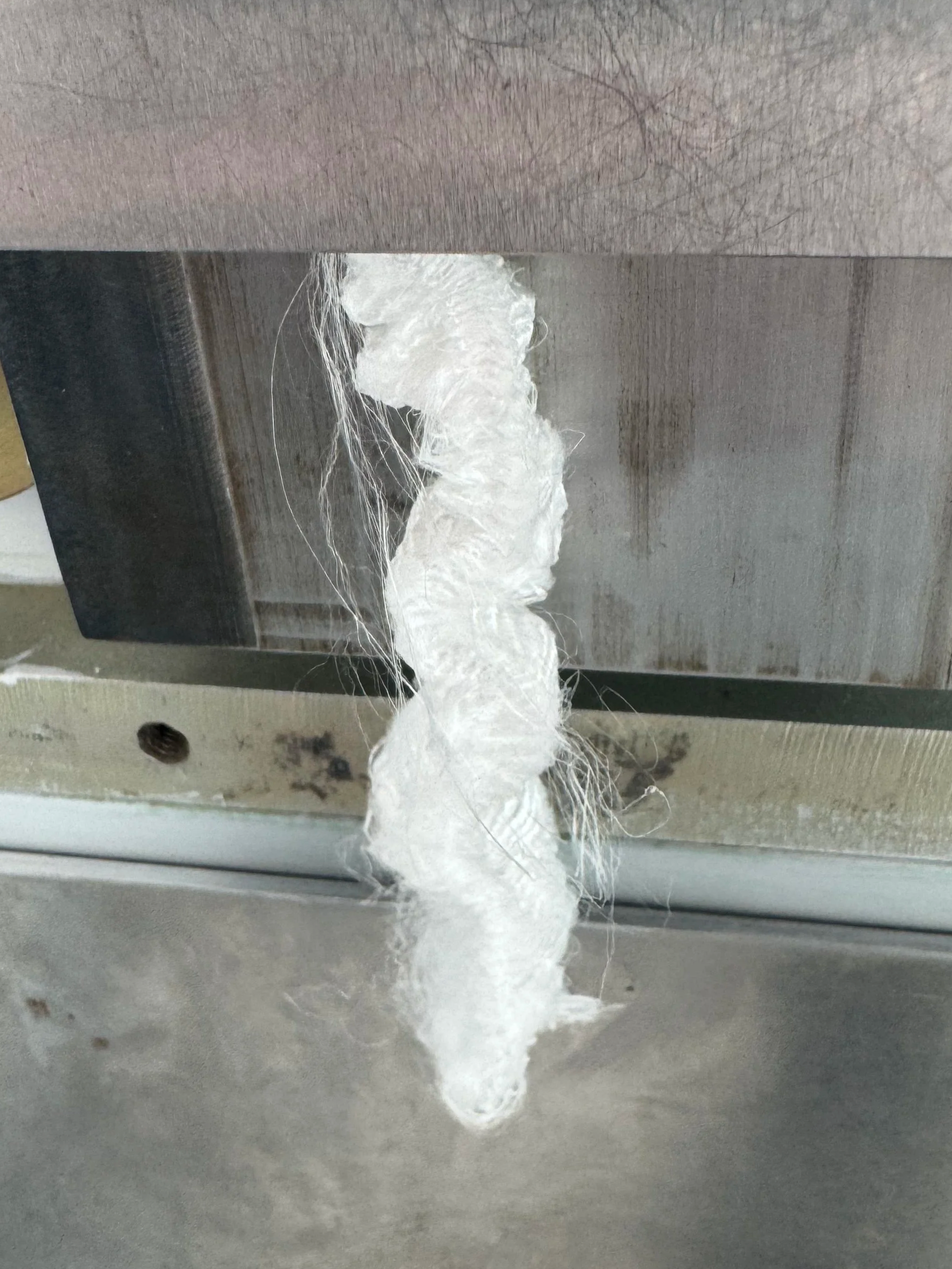
In the world of nonwovens, these man-made fibres require crimp, that is, a wave-like structure to be set into the extruded filament. This is achieved by stuffing the filament into a tapered box whilst softening it with heat. This induces small-scale buckling of the filament, giving rise to repetitive wave crests. However, for this to work, there needs to be a significant filament cross-section so that it buckles only in a single plane perpendicular to the filament’s length.
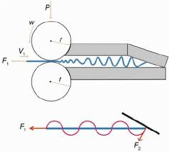
Filament tow entering a tapered stuffer box crimper
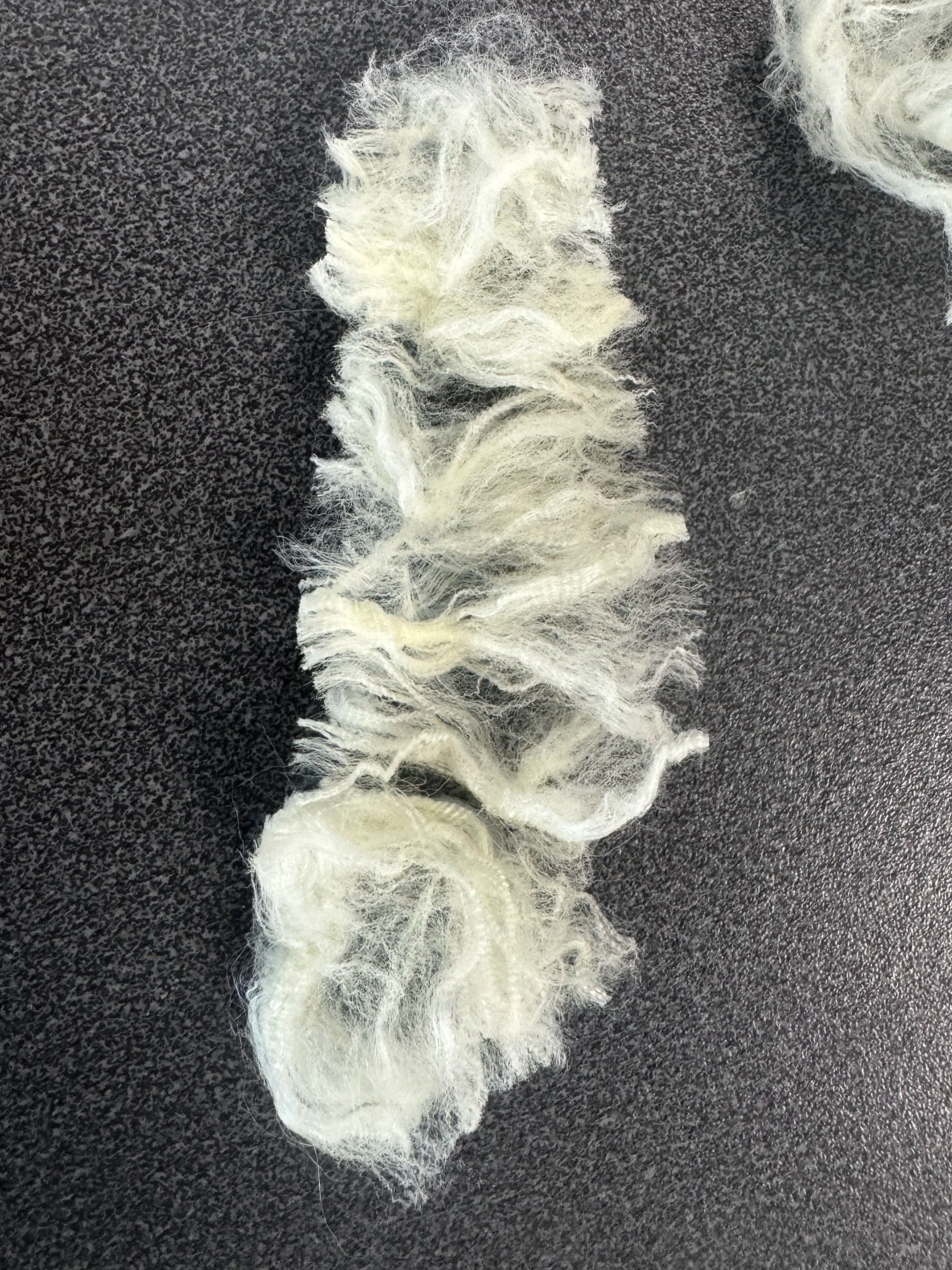
Our problem here was that we couldn’t produce enough of a cross-section during extrusion for this crimping process, so we needed a way of plying lengths of filaments into a larger tow of filament. Initially, this was achieved by manually plying the filament together by wrapping it around two clamps, as shown in the image below. However, this was very time-consuming and required a more efficient way to achieve this result. As a direct result of this slow process, the yield of crimped filament was in the range of the tens of grams, when realistically, hundreds of grams are needed for fabric prototyping trials.
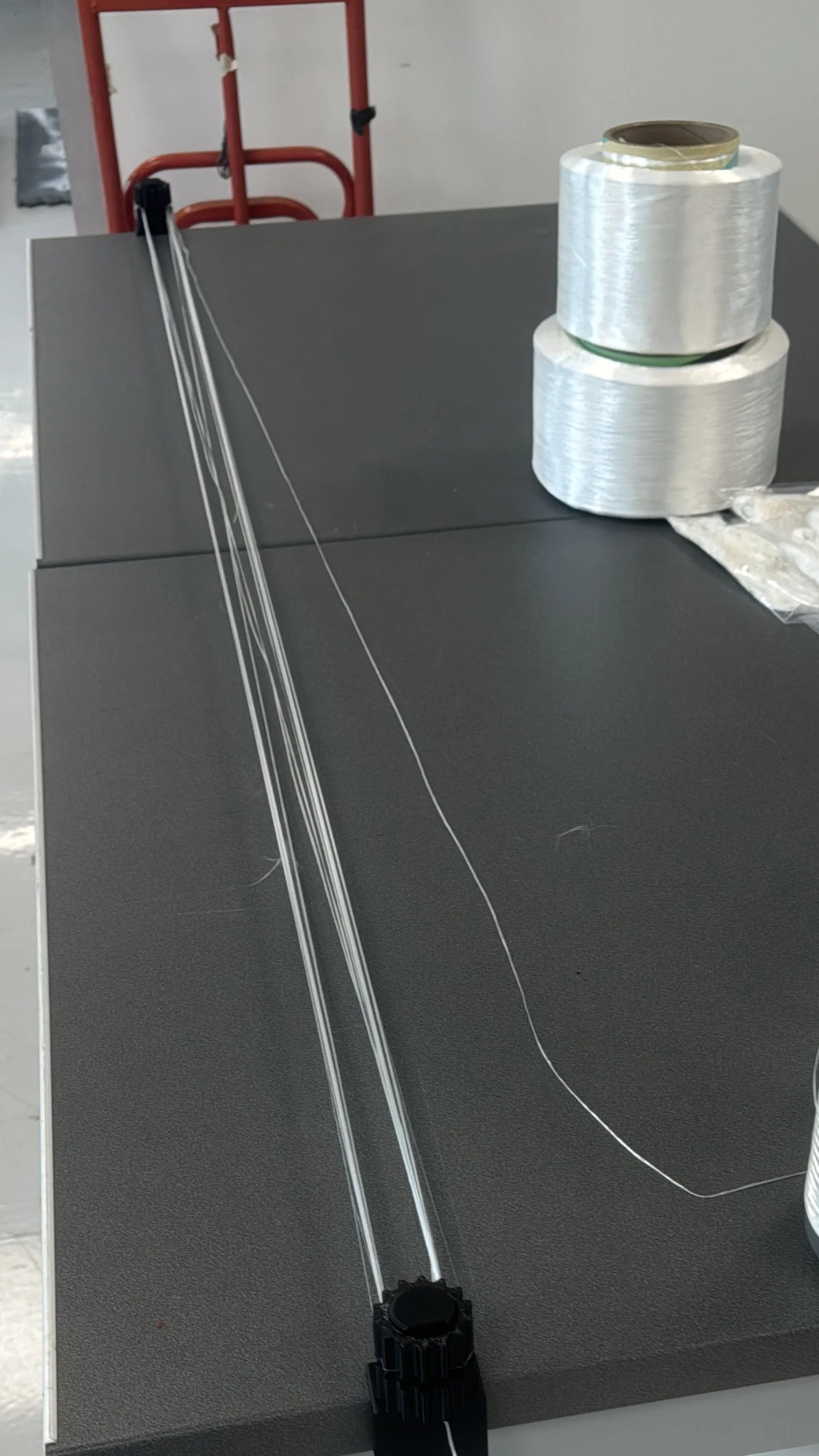
Manually plying extruded filament together to increase the tow cross section
The objective of the project is to design a machine that can reduce the labour required to increase the tow cross-section sufficiently for stuffer box crimping. This led to the following design constraints:
Simplify the flow process of going from extruded filament to a “crimpable” tow
Some form of semi-automated winding mechanism
Ability to create at least 2 metre tow lengths for crimping
Primarily produced from 3D printed components
Design Concept
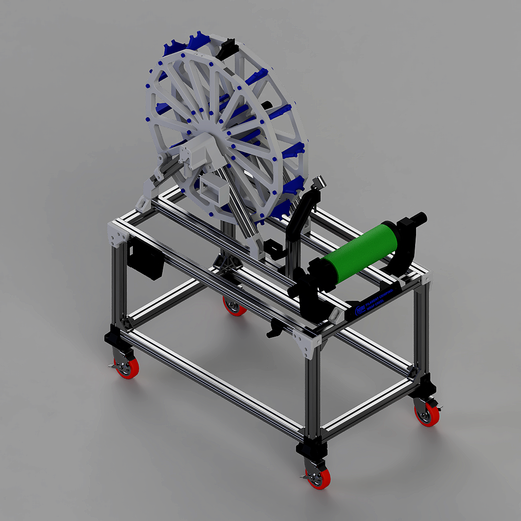
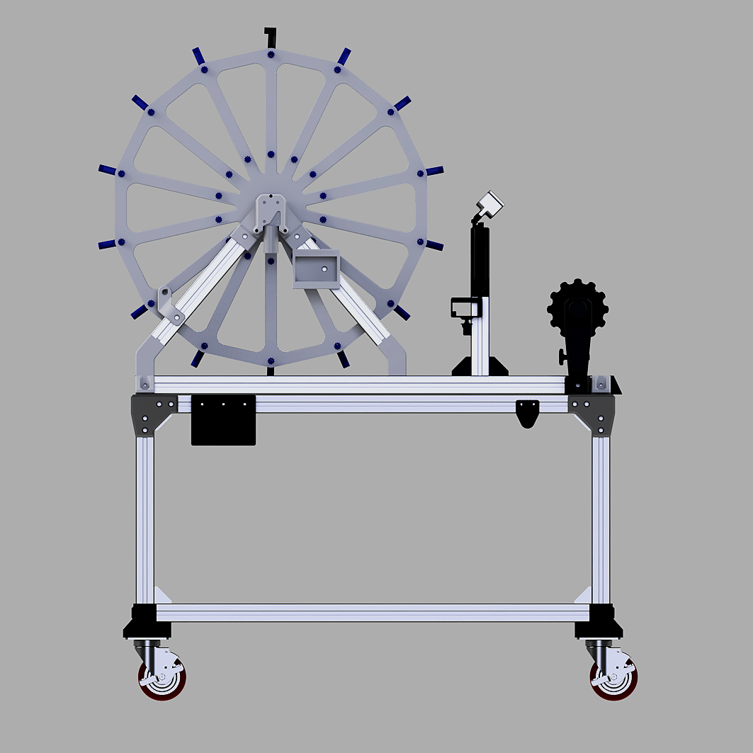
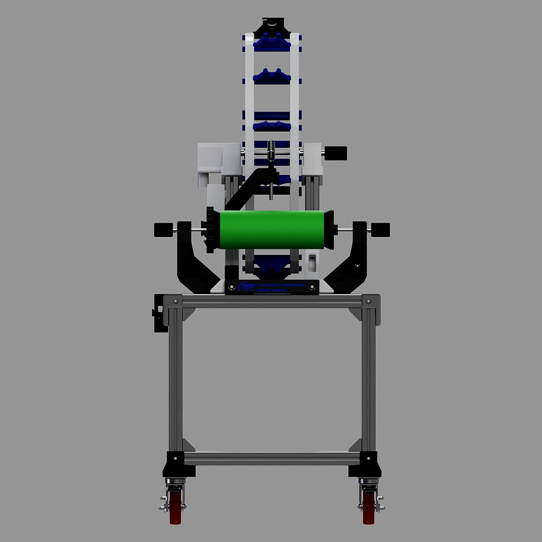
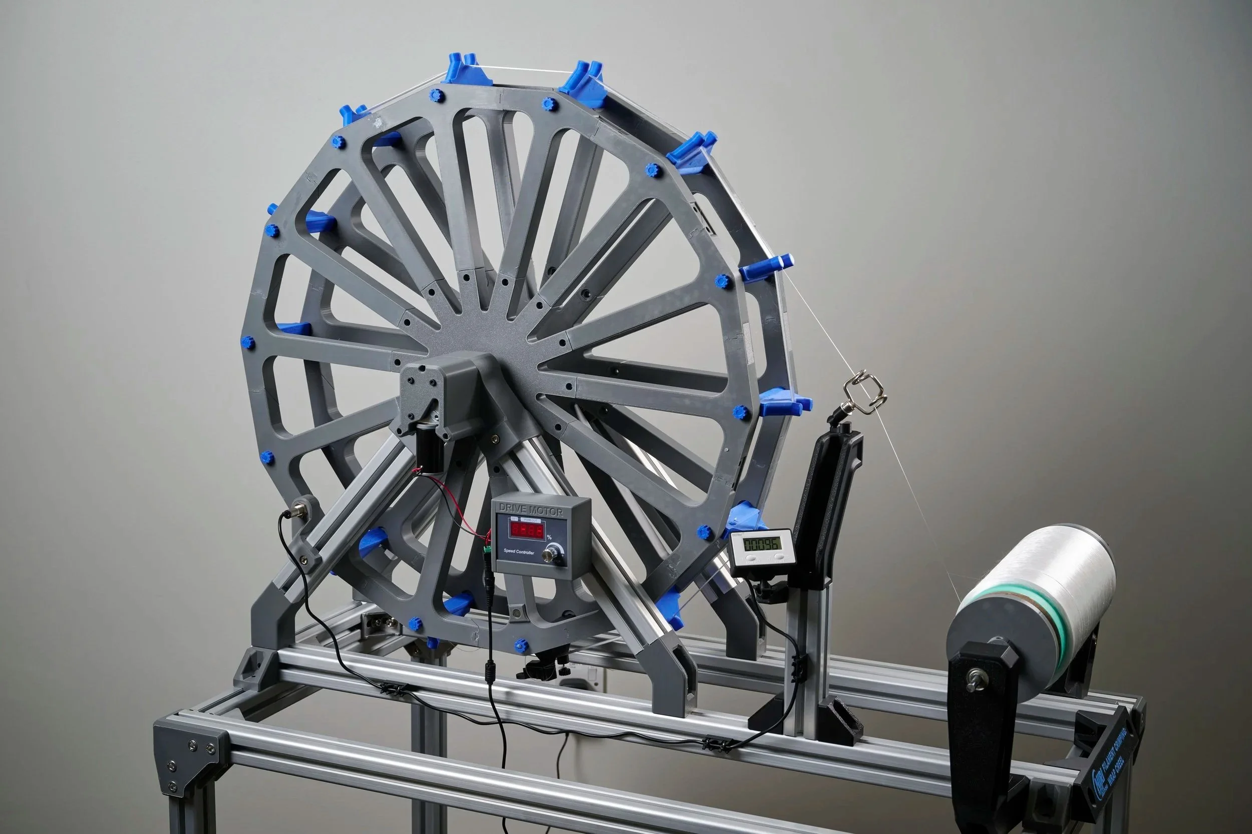
The concept is inspired by a filament wrap creel, which is used in the industry, typically to measure the linear density of the filament. The solution comprises a filament unwinder with a 2.1-metre circumference polygonal creel wheel to which the filament attaches. Capable of rotating at up to 30 RPM by a DC motor, the creel can create a 2.1 metre length with a suitable cross-section for stuffer box crimping. Key features include:
Roller bearing-supported filament core unwinder with conical clamps
Variable speed motor-driven polygonal creel wheel with filament clamp
Hall-effect rotation counter to determine the number of filament wraps
Concept Features: In-Depth
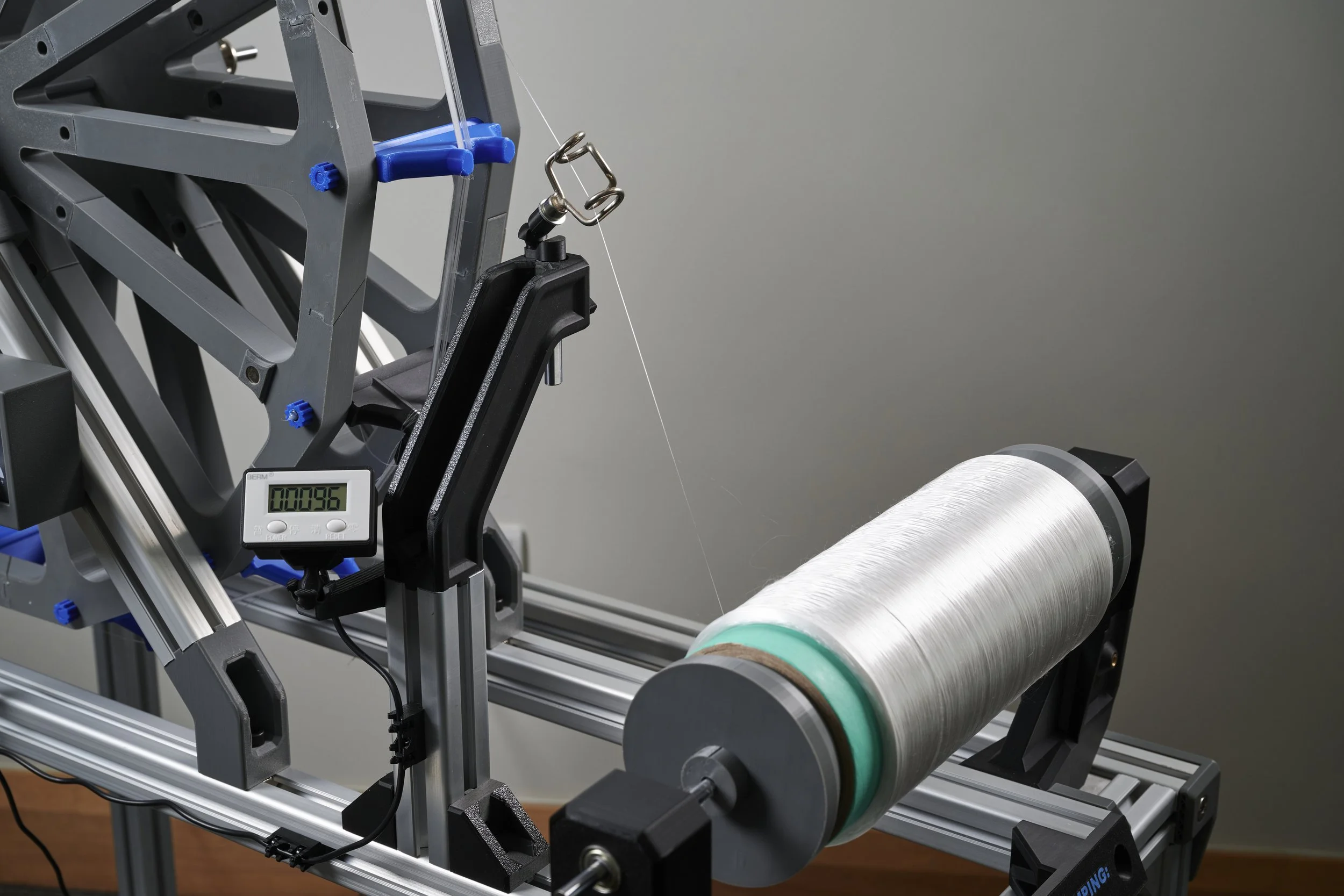
Roller Bearing Filament Core Unwinder
It was essential to have an unwinding system that was versatile enough to accommodate various spool core diameters and sufficiently simple for insertion. Conic-section clamps cater for this by allowing cores with diameters between the maximum and minimum conic-section diameters. Minimising the unwinder’s rolling friction is crucial for unwinding multifilament that is typically low-strength and low in cross-sectional count; such filaments may only be able to resist forces of tens of grams. To reduce friction and, consequently, excessive tension on the multifilament, roller bearings were installed in the printed framework. This allowed the core to rotate freely with negligible resistive loading on the filament.
Variable Drive Speed Filament Creel
At full speed (30 RPM), the creel is typically capable of creating an 80K Dtex tow in 12.5 minutes from commonly used 3 Dtex filament:
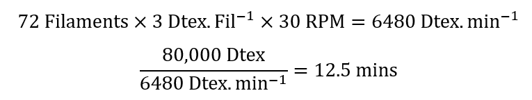
Calculation for run time to generate 80K tow
This significantly reduced the time required to make the tow for crimping compared to the old method. A pulse-width modulation (PWM) controller is used to enable variable-speed control of the DC creel motor. Variable-speed control of the creel is integral, as it allows the user to gradually speed it up during the first few rotations, ensuring that the force required to accelerate the core's inertia doesn’t break the filament. It also allows the operator to monitor individual filament fraying that may otherwise cause the entire multifilament feed to break at higher speeds.
Hall-Effect Sensor Wrap Counter
A Hall-Effect sensor was used in conjunction with a digital counter to display the number of creel rotations (equivalent to the cumulative wraps of the filament) to the operator. The decision to go with an electronic solution over a mechanical one was based on reducing the number of components that could fail. A mechanical counter is likely to undergo many cycles of use, increasing the risk of fatigue failure over time.
Design for Additive FDM
From the project’s inception, the manufacturing constraints were well defined by the processes available. With additive manufacturing as the predominant production method, the design language had to accommodate it.
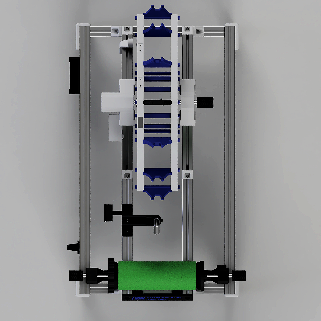
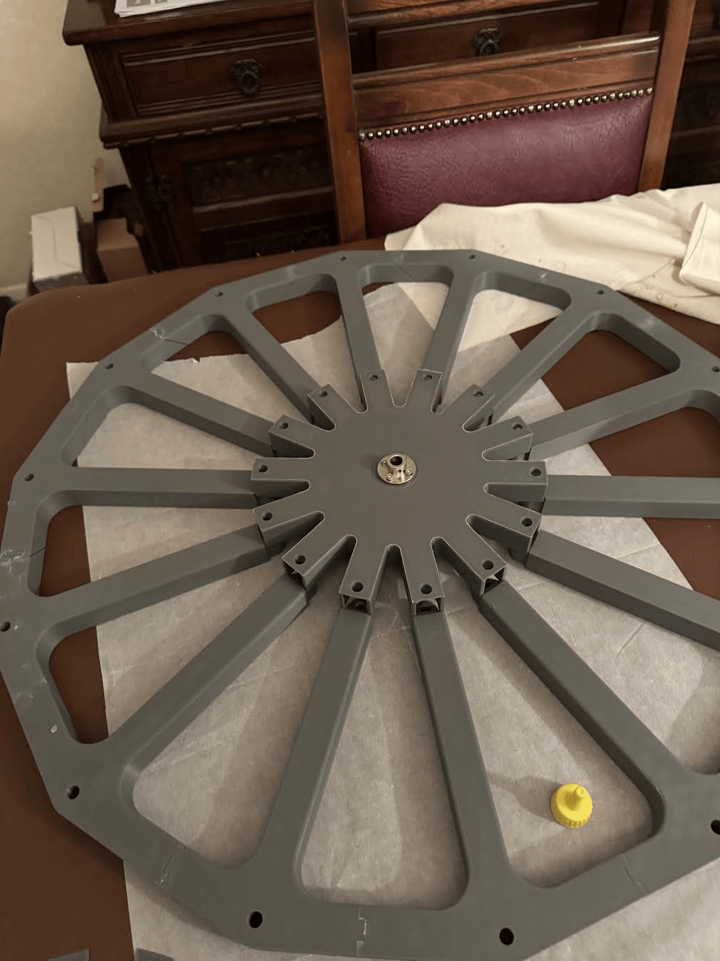
The creel wheel is designed as a 14-sided polygon with an effective circumference of 2.1 metres. To print the polygon on a 25.6 x 25.6 cm2 bed area, it was split into 14 spoke segments branching from a central hub. The spokes were designed as alternating positive-negative pairs with alignment joints and lap joints designed into them. Care was taken to ensure all overhang features were designed with a minimum overhang angle of 45 degrees to ensure printing without support material.
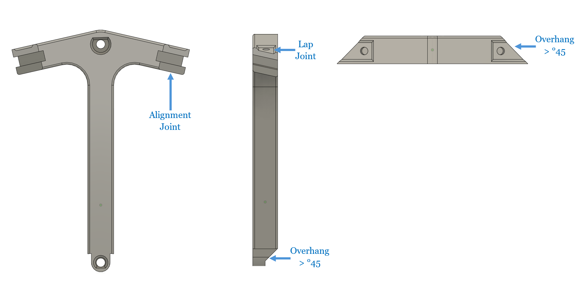
Spoke segment with alignment joints, lap joints and >45 degree overhangs for supportless printing
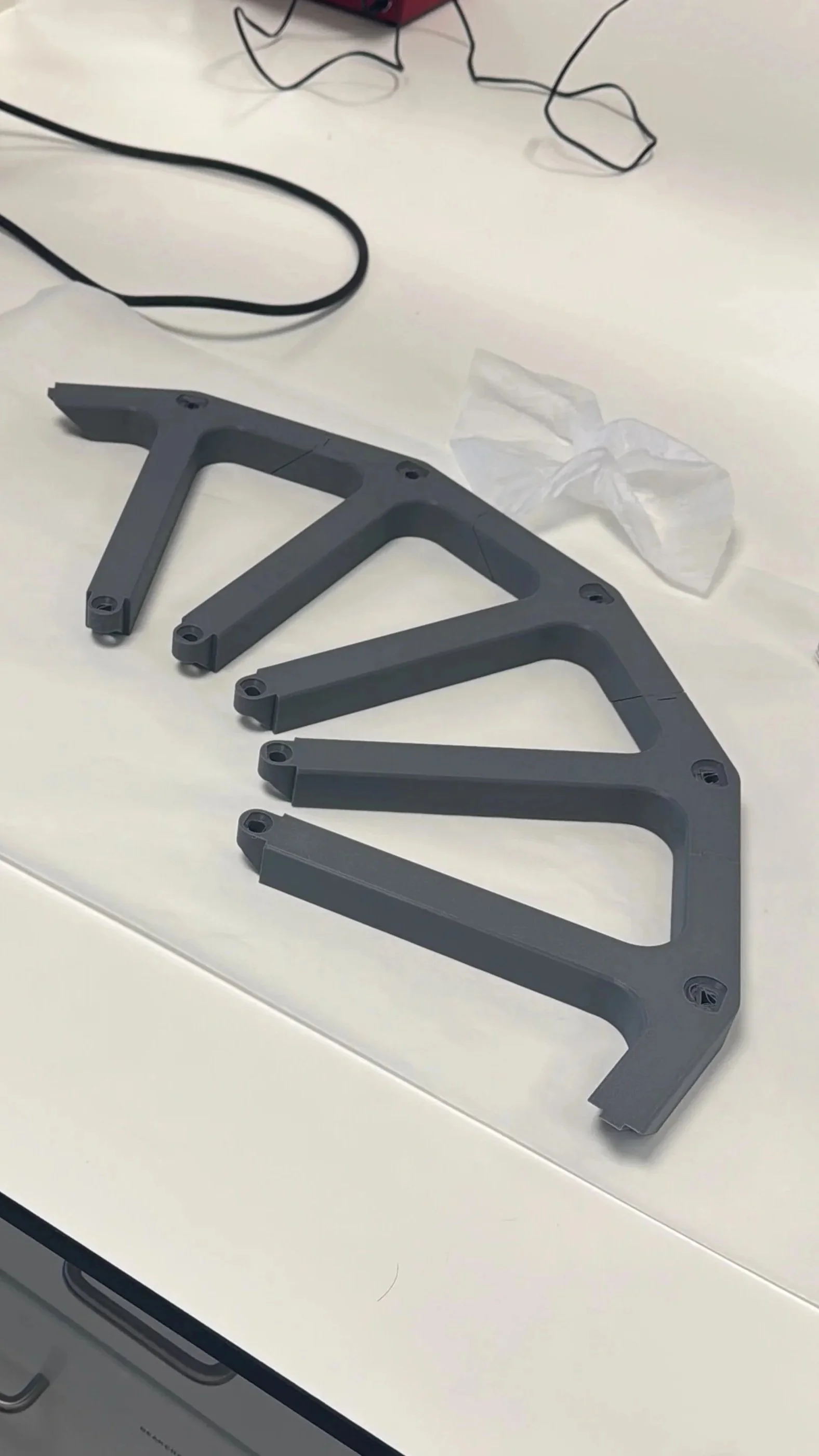
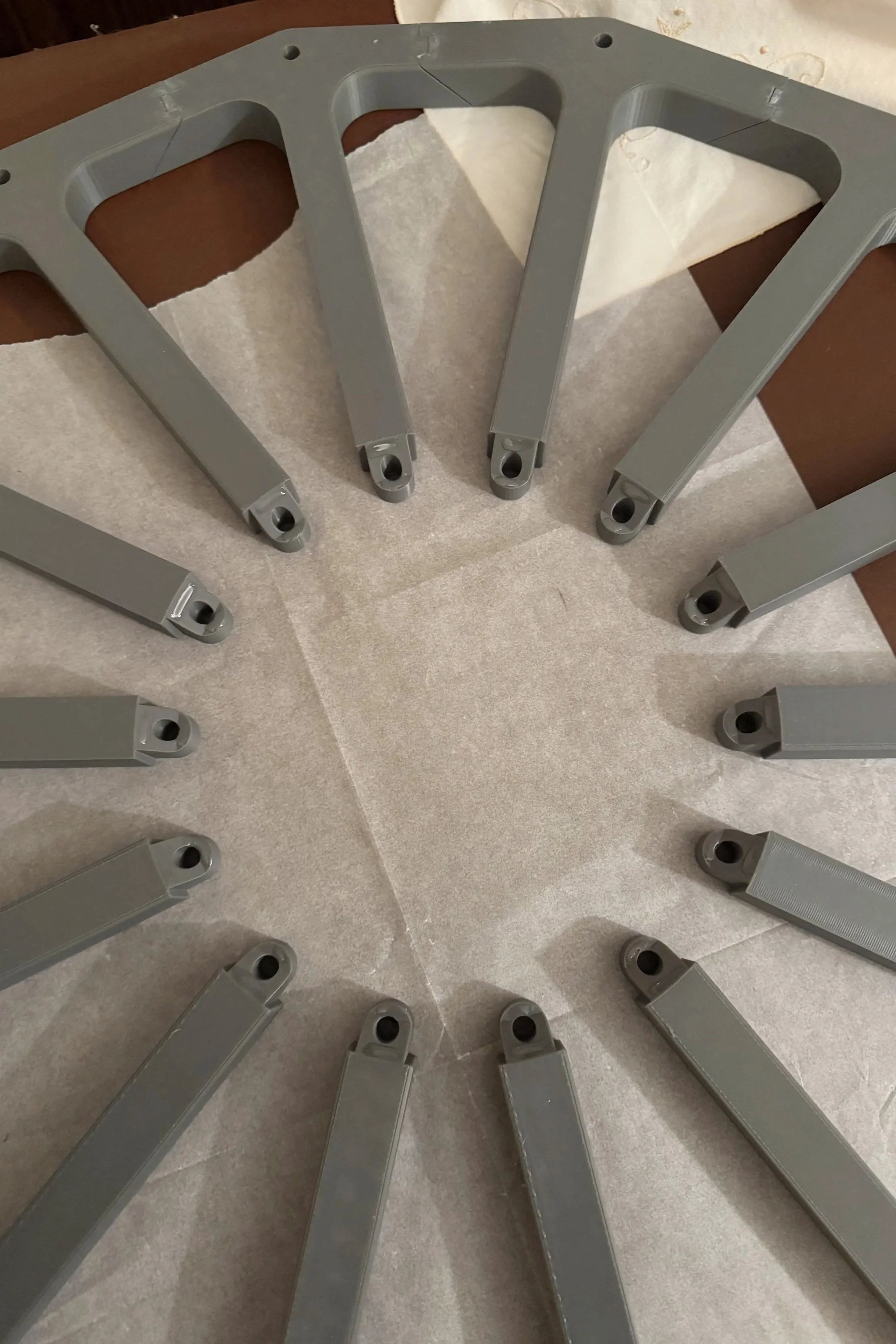
Segments were bonded together with a PU-based superglue, using alignment and lap joints. Once cured, the central axle hub was affixed to the spoke assembly using PU superglue.
Structural Framework Constructed from Aluminium Extrusion
Aluminium 40:40 box extrusion section was used to make up the framework supporting the creel-tow winding system. Although the loads the framework must support are relatively low, aluminium extrusion offers an excellent strength-to-weight ratio at a competitive price point. Furthermore, extrusions are versatile; they can be cut into various lengths and rigidly fastened together at numerous angles to create adjustable structures. Further complementing this versatility is the ability to easily combine additive manufacturing to create bespoke fixtures and components that can attach directly onto the extrusion.
Finished Equipment

Evaluation
Summary
This filament wrap creel was developed to automate the controlled increase of filament tow cross-section, a necessary pre-processing step to make a subsequent crimping operation viable. The previous manual tow expansion method was prohibitively time-consuming, rendering the overall process impractical. This system enables repeatable, low-tension tow handling while significantly reducing processing time, allowing the crimping process to be applied at scale.
Amendments for Future Iterations
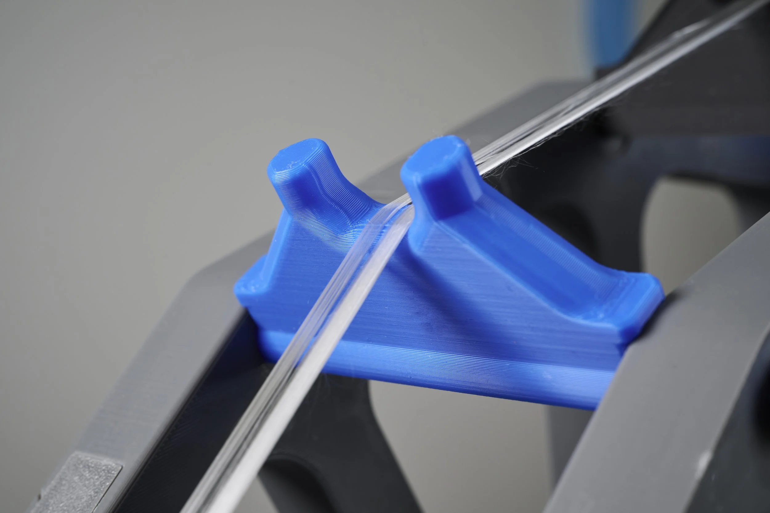
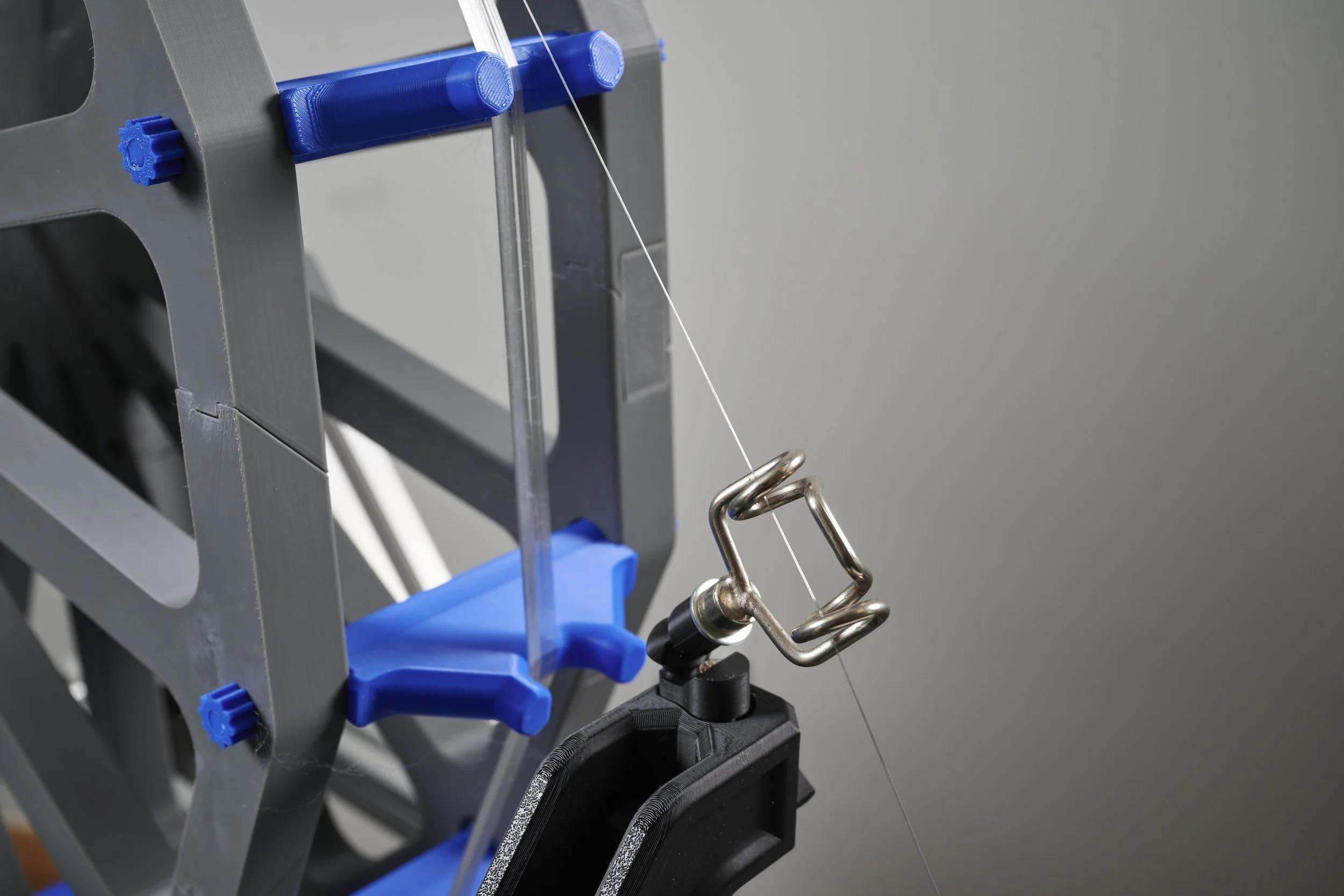
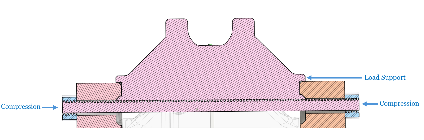
To reduce the moment of inertia of the creel, and consequently the torque on the drive motor, the creel’s blue struts for the two collections were entirely 3D printed. Although this reduces the inertia on the creel, it does reduce the structural integrity somewhat. Designed into the struts' interfacing geometry is a load-bearing lip support that forms to the curvature of each spoke's apex. Combining this with the clamping force provided by the fastening nuts to prevent their translation and rotation provides a suitable level of support to avoid failure during use. However, the 3D-printed thread and nuts may degrade over time during maintenance, assembly and disassembly,
3D-printed tow collection strut
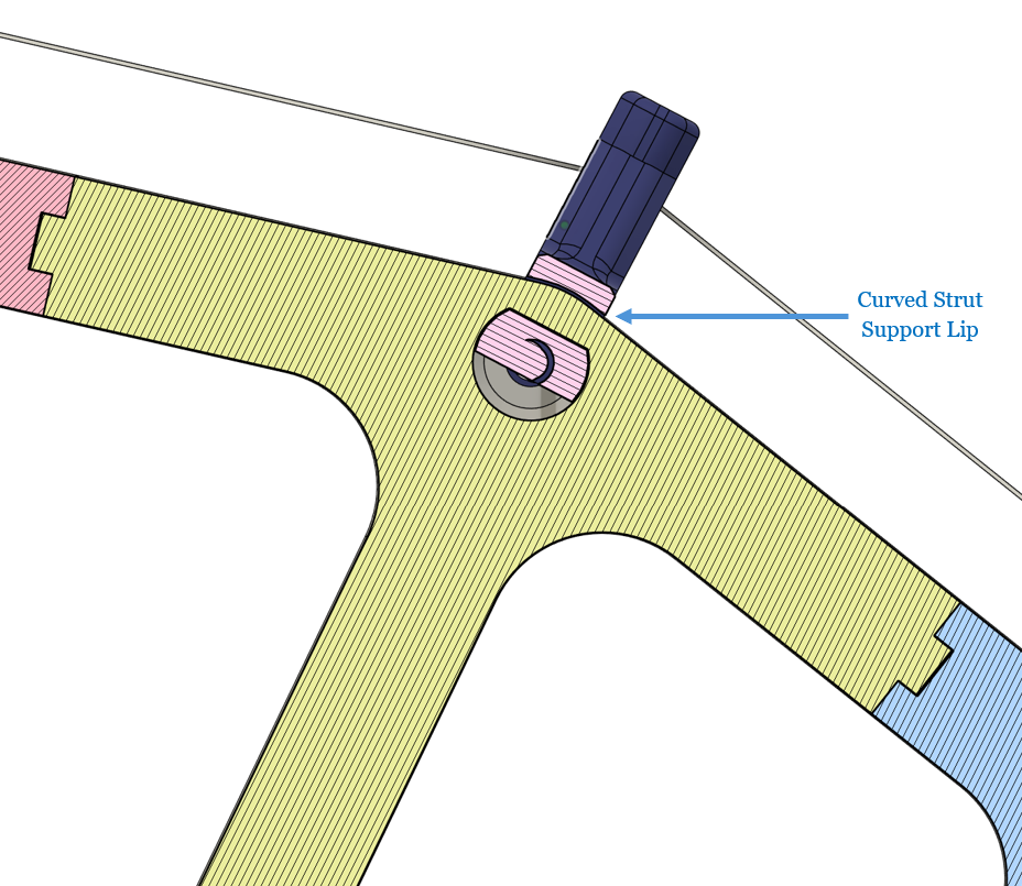
Support strut with curved support lip matching spoke segments curvature
To improve upon this, future iterations should replace the printed thread for the support strut with an equivalent stainless steel threaded rod and Nylock nuts. This will aid in improving the longevity of the equipment.