Three Point Bending Fixture
Design Brief & Constraints
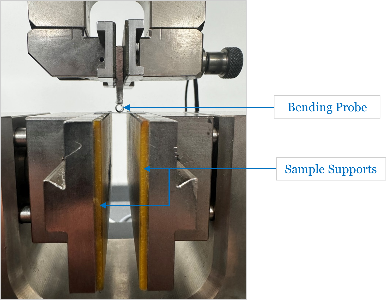
Previous 3-point bending set-up
The above image shows the previous setup employed for testing the bending properties of card-backed foam composites & thin plastics. Used in applications such as mounting photos and building architectural models, bending stiffness and resistance are critical to end product performance.
The previous set-up was compromised by many shortcomings, including:
Operator variation in setting the bending probes zero position, leading to variable displacement measurements and the potential for equipment damage, as zeroing the probe requires accurate positioning above the specimen supports.
Operator variation in centreing the bending length span about the bending probe. Currently, each support adjusts independently about the central point (the bending probe), leading to potential off-centre point force application.
The bending probe and supports do not adhere to any specific testing standards, i.e. BS EN 178-2003
The objective of the project is to develop a standardised fixture that improves the ease of set-up, repeatability and consequently produces more robust testing results. This led to the following design constraints:
Designed in accordance with BS EN 178-2003 – Plastics: Determination of Flexural Properties
Designed for additive manufacture, incorporating off-the-shelf components
Simplistic assembly and disassembly
Improves upon previous set-ups’ reproducibility, repeatability and ease of set-up
Design Concept
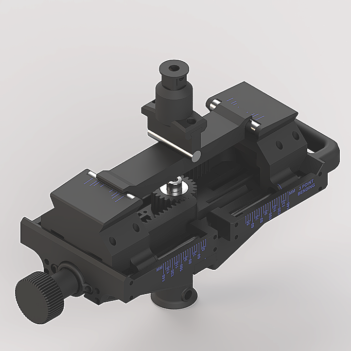
Isometric Render of Three - Point Bending Fixture Concept with Zeroing Plate
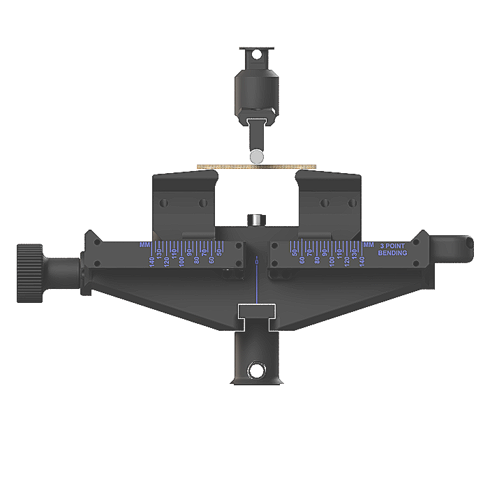
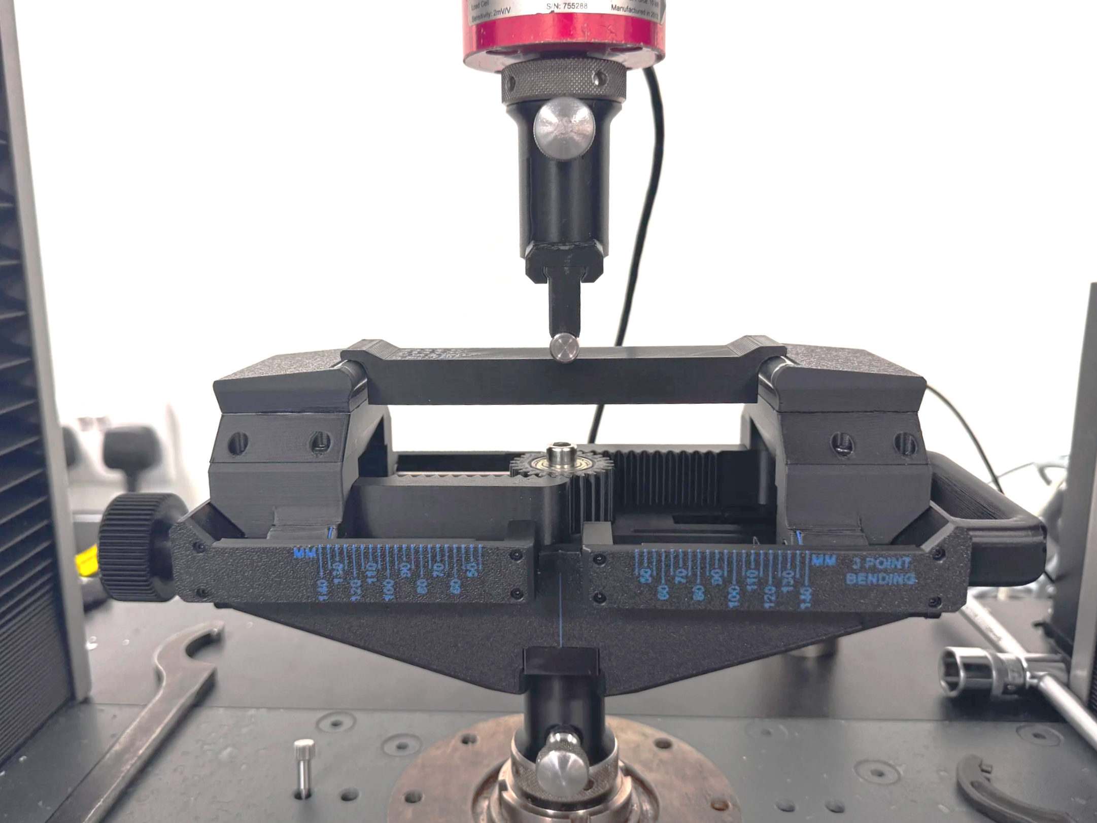
Three-Point Fixture with Specimen Mounted
The concept centres around providing operators with a repeatable and easy to use fixture conforming to BS EN 178-2003. Key features include:
Easy to adjust support span to cater for various specimen lengths
Interchangeable support bollards for different support radii
Built-in span scale
Interchangeable specimen probe radii
Specimen probe ‘zeroing’ plate
Concept Features: In-Depth
Adjustable Support Span
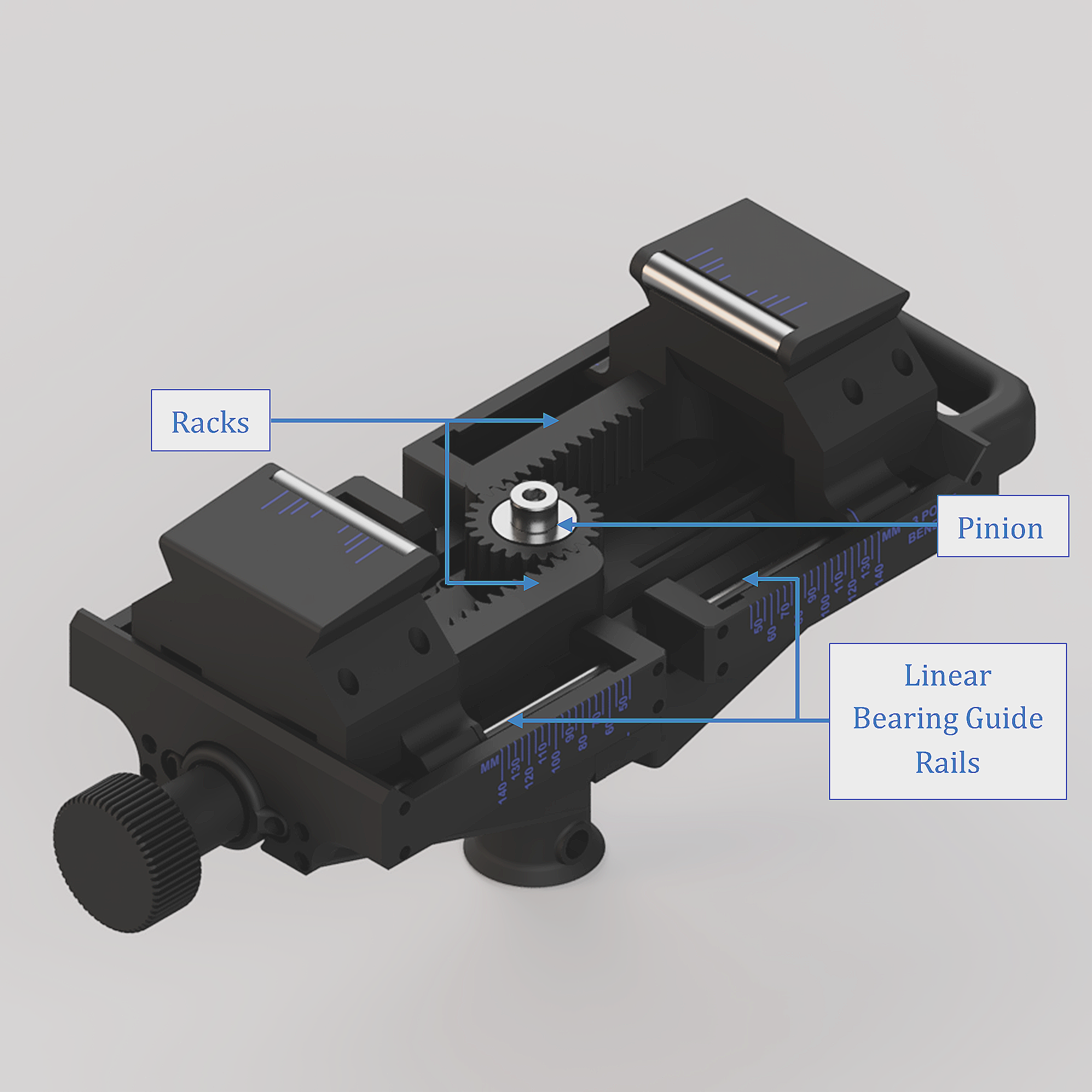
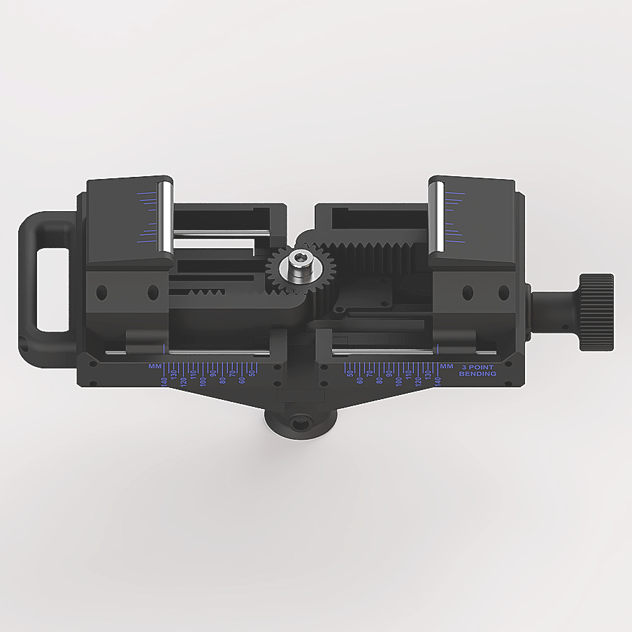
Isometric View Highlighting Key Motion Components
Section cut-away exposing lead screw drive mechanism
A centralised pinion gear couples the two specimen support bollards via their respective racks. A lead screw drives the translation of the driven support via an embedded lead nut. This results in symmetrical adjustment of both supports about the centre of the span.
Interchangeable Support Bollards
Specimen alignment markers for various coupon widths specified within BS EN 178:2003
Bollard supports are designed to be interchangeable. This allows operators to swap between various support radii, described within the standard, depending on the specimens thickness. Supports are marked with standard specimen widths to aid the operator with centralising the test coupons.
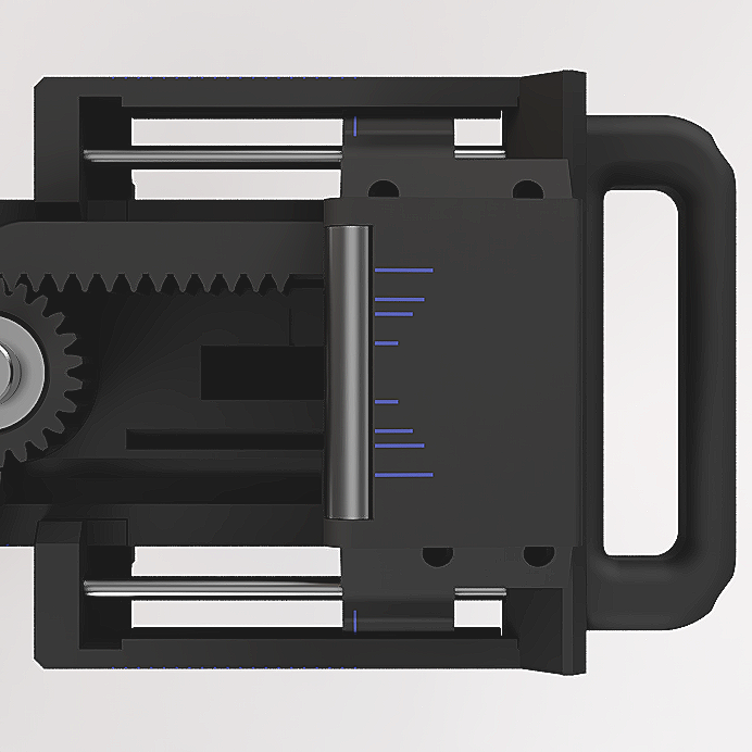
Built-in Span Scale
Incorporated onto both sides of the fixture is a span scale, allowing for repeatable & accurate adjustment of the support span around the central “zero” point of the specimen span. The span is easily adjusted in 5 mm increments via a knob that engages the lead screw, a blue indication marker on the support bollard allows the operatore to visually read off the span setting
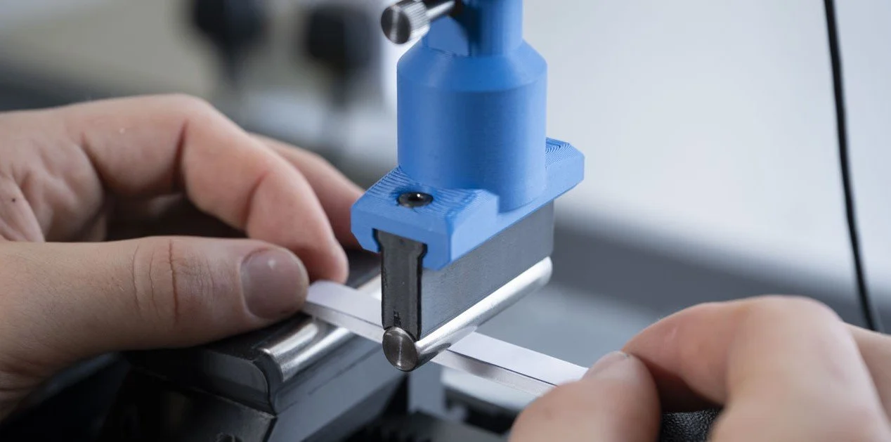
Interchangeable Specimen Probe Radii
The bending probe is designed so inserts of differing radii, in accrodance with BS EN 178:2003, can be inserted into the mounting attached to the universal testers cross-head. This caters for different material thicknesses.
Specimen probe ‘zeroing’ plate
The fixture is provided with a plate that fits over the span of the supports. This allows the operator to manually maneouver bending probe into the ‘zero’ datum position in a repeatable manner allowing for repeatable, accurate bending displacements to be measured.
FEA Study - Displacement
Set-up
To ensure the apparatus improved on the accuracy of the previous set-up, a static structural FEA study was carried out to ensure the fixtures overall compliance was negligible relative to the foam board. The FEA study was set-up as follows:
Materials
Polyethylene - Foamboard is typically made from aerated polyethylene
Stainless Steel - The leading edge of the bollard supports comprise of 10 mm diameter polished stainless steel dowels
PET - The printed components are produced from polyester (PET)
Simplifications
All non-structural components were removed from the study
Constraints
Fully fixed support at the fixture collar to resist translation and moment
Specimen constrained at either end for Y and Z axis translation, X translation free
Load
Singular point load applied at the mid span
200 N magnitude to coincide with maximum measurement capacity of the load cell
Results
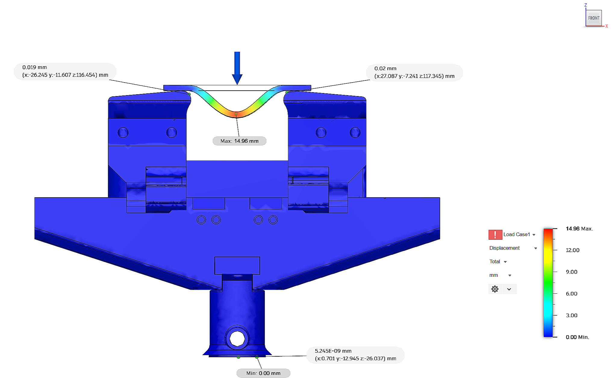
Deformations of printed PET plastic components under 200 N applied point loading
The displacement of the printed components is negligible relative to that if the foam board during all points of load application. Therefore, the compliance of the system is considered to be insignificant and the design suitable for the application of testing low density plastic and foam coupons.
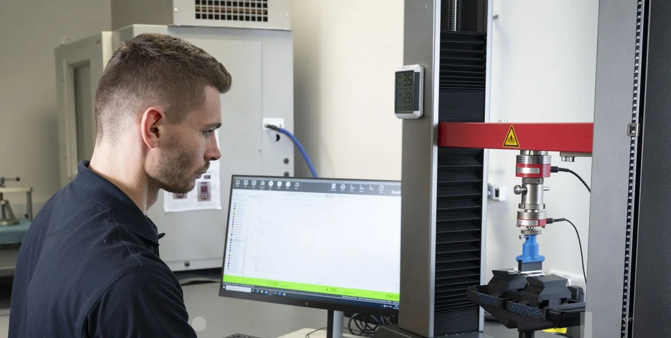
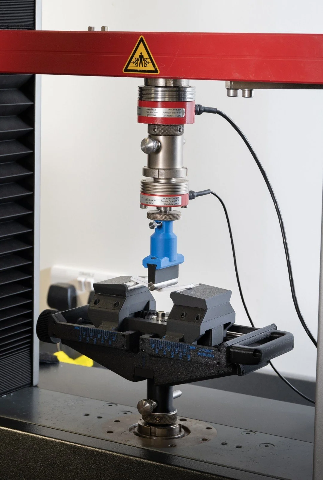
Finished Prototype